

Chapter 1. Basic Electricity
1.1 Voltage, Current, and Resistance
(1) Voltage (symbol V, unit Volt) is the "pressure" that drives the flow of electric charge. Think of it like the height of a water tower—the higher the tower, the greater the water pressure, and the stronger the force of the water flow. For example, a 9V battery provides a greater driving force than a 1.5V battery. However, higher pressure means stronger force, so high-voltage applications (such as household 110V or 220V) usually require stricter safety protection.
(2) Current (symbol I, unit Ampere) is the "rate" of electric charge flow. In the analogy of a water pipe, it's the amount of water flowing per second. The thicker the pipe and the higher the water pressure, the more water flows per unit time; similarly, the thicker the wire and the higher the voltage, the greater the current. For example, the 2A or 3A markings on a mobile phone charger refer to the maximum current output it can provide; the higher the number, the faster the charging speed.
(3) Resistance (symbol R, unit Ohm, symbol Ω) is the "resistance" that hinders the flow of electric charge, just like the thickness of a water pipe—the thinner the pipe, the slower the water flows; the greater the resistance, the smaller the current. Resistors are either intentionally designed or have the tiny resistance of the wire itself, so they are almost ubiquitous in circuits.

1.2 Direct Current and Alternating Current
Electricity can be divided into two types: direct current (DC) and alternating current (AC). Direct current flows in a constant direction, and its voltage is stable. Examples include the 5V output of a battery, a USB charger, and a car battery (12V). Alternating current flows in a periodically reversed direction, and its voltage exhibits a sinusoidal wave pattern. Household 110V/220V sockets use AC, with a frequency of 60Hz or 50Hz (changing 60 or 50 times per second). Most electronic products operate using DC internally, thus requiring a rectifier circuit to convert AC to DC. Understanding the difference between DC and AC is fundamental to reading circuit specifications—for example, seeing "DC 5V/2A" indicates a DC output of 5 volts with a maximum of 2 amps, while "AC 110V/60Hz" indicates a household AC power supply of 110 volts at 60Hz.
1.3 Series and Parallel Circuits
When multiple components are connected together, there are two basic ways: series and parallel. In a series circuit, the components are connected end-to-end to form a single path, and the current flows through each component sequentially. The total resistance is the sum of the individual resistances (R = R1 + R2 + R3), and the current is the same at all points in the circuit. In a parallel circuit, the components are connected side-by-side to form multiple paths, and the current is split across each branch. The reciprocal of the total resistance is equal to the sum of the reciprocals of the individual resistances (1/R = 1/R1 + 1/R2 + 1/R3), and the voltage across each branch is the same.

Chapter 2. Passive Electronic Components
Electronic components can be broadly categorized into "passive components" and "active components." Passive components cannot actively amplify signals or control the direction of current; they can only passively respond to the current flowing through them—performing functions such as current limiting, energy storage, and filtering. Passive components are typically indispensable basic parts in all circuits, and can be found on any circuit board. Passive components mainly include resistors, capacitors, and inductors, and this chapter will introduce their functions, characteristics, and applications one by one.
2.1 Overview of Three Passive Components
(1) A resistor is a component that limits the amount of current, converting electrical energy into heat. For example, a resistor connected in series in an LED light circuit limits the current flowing through the LED to prevent it from burning out.
(2) A capacitor is a component that stores electrical charge. It can charge and discharge quickly and is commonly used for filtering (smoothing voltage ripples), coupling (transmitting AC signals but isolating DC), and energy storage.
(3) An inductor stores magnetic energy through electromagnetic induction and has the characteristic of "opposing sudden current changes." It plays a crucial role in power supply filtering, transformers, and motor drives.

These three components share an important common characteristic: they are all "linear components," meaning there is a linear relationship between voltage and current. This allows their behavior to be accurately described by simple mathematical formulas, making circuit analysis feasible. In contrast, active components (such as diodes and transistors) are mostly nonlinear components, exhibiting more complex behavior, but also enabling them to perform richer functions such as amplification and switching. Therefore, understanding the characteristics of passive components is a necessary prerequisite for understanding the working principles of active components.
Chapter 3. Active Electronic Components
Active components are the core of modern electronics. Unlike passive components, active components can actively control the direction and magnitude of current flow, performing functions such as rectification, amplification, and switching. They are the foundation of all amplifiers, logic circuits, and microprocessors. From a tiny diode to a CPU containing tens of billions of transistors, the development of active components has driven the entire information age. This chapter will begin with the simplest diode, gradually introducing transistors and integrated circuits to establish a complete understanding of the working principles of active components.
3.1 Diodes: Unidirectional Conduction Components
A diode is the simplest active electronic device, consisting of a PN junction formed by combining P-type and N-type semiconductors. The P-type semiconductor contains numerous holes (positively charged carriers), while the N-type semiconductor contains numerous electrons (negatively charged carriers). When they are joined, a depletion region is formed at the junction, creating a built-in electric field. This structure gives the diode its unidirectional conductivity: it conducts when forward biased (P-connected to positive, N-connected to negative) and is cut off when reverse biased, much like an electronic one-way valve.
The most common application of diodes is "rectification"—converting alternating current (AC) to direct current (DC). A bridge rectifier consisting of four diodes can convert bidirectional AC to unidirectional pulsating DC, which is the basic architecture of all AC-to-DC power supplies. Besides rectifier diodes, LEDs (light-emitting diodes) are also commonly used, utilizing their characteristic of emitting light when forward-biased, and are widely used in displays and lighting. Zener diodes, on the other hand, utilize their reverse breakdown characteristics to maintain a stable voltage, and are used for voltage protection and reference voltage generation.
3.2 Transistors: Switches and Amplifiers
Transistors are one of the most important inventions of the 20th century. Their emergence replaced bulky and power-consuming vacuum tubes, ushering in the era of solid-state electronics. Transistors can be divided into two main categories: BJTs (Bipolar Junction Transistors) and MOSFETs (Metal-Oxide-Semiconductor Field-Effect Transistors). A BJT consists of two PN junctions (NPN or PNP structure) and has three terminals: base (B), collector (C), and emitter (E). It amplifies current by controlling a larger collector current with a small base current. A MOSFET, on the other hand, is the absolute mainstream in modern ICs. It is composed of a metal-oxide-semiconductor stack and has three terminals: gate (G), drain (D), and source (S). Unlike the current control of BJTs, MOSFETs are voltage-controlled devices—the gate voltage controls the conduction level of the channel between the source and drain. Due to their extremely high gate input impedance (consuming almost no power), MOSFETs are very suitable for large-scale integrated circuits. Almost all of the billions of transistors inside modern CPUs are MOSFETs. Moore's Law has lasted for decades precisely because the size of MOSFETs can be continuously reduced.

Transistors operate in two basic modes in circuits: switching and amplification. As a switch, a transistor toggles between cutoff (non-conducting) and saturation (fully conducting) states, representing the 0s and 1s of digital logic—the foundation of digital circuits. As an amplifier, a transistor operates in the linear region, amplifying small input signals into larger output signals, used in analog circuits such as audio amplifiers, radio transmitters, and sensor signal processing. The same transistor can achieve drastically different functions by setting its operating point differently.
3.3 Integrated Circuits (ICs)
Integrated circuits (ICs) are miniature circuits that integrate a large number of transistors, resistors, capacitors, and other components onto a single semiconductor chip. A modern CPU may contain tens of billions of transistors, all fabricated on a silicon chip the size of a fingernail. The invention of ICs has enabled electronic products to be drastically reduced in size, power consumption, and reliability, forming the technological foundation for the information age. Without ICs, there would be no personal computers, smartphones, or the Internet.
ICs can be categorized into various types based on their functions. Operational amplifiers (Op-Amps) are the core of analog circuits, capable of performing various mathematical operations such as amplification, comparison, filtering, and integration. Logic ICs (such as the 74 series) contain basic logic gates and are the building blocks of digital circuits. Microcontrollers (MCUs) integrate the CPU, memory, and I/O into a single chip; Arduino's ATmega328 and STM32 are typical MCUs. More complex SoCs (System on Chip), such as mobile phone processors, integrate the CPU, GPU, modem, and image processor into a single chip.

Chapter 4. Analog and Digital Circuit Design
Electronic circuits can be divided into two main categories: analog circuits and digital circuits. Analog circuits handle continuously changing signals, such as the sound waveform received by a microphone or the voltage changes of a temperature sensor; digital circuits, on the other hand, handle discrete 0 and 1 signals and are the foundation for the operation of computers and all digital devices. Each has its own application scenarios and design philosophies, and understanding their differences and complementary relationships is essential to understanding electronic circuits. This chapter will introduce the basic principles of both types of circuits and explain how they are interconnected through ADC/DAC conversion.
4.1 Analog Circuits: Processing Continuous Signals
Analog circuits process continuously changing voltage or current signals, which can take on an infinite number of values, accurately reflecting the continuity of the physical world. The core component of analog circuits is the operational amplifier (Op-Amp), which, through different combinations of resistors and capacitors, can perform various functions such as amplifiers, filters, integrators, differentiators, and comparators. For example, signal amplification in audio systems, modulation and demodulation in radio waves, and signal conditioning in sensors all fall under the category of analog circuits.
The design challenges of analog circuits lie in dealing with "noise" and "distortion." Because the signal is continuous, any interference will be directly superimposed on the signal, and noise will be amplified with each stage of amplification. This is why high-quality audio equipment is extremely particular about power supply purity, grounding, and shielding. In contrast, digital signals only have two states, 0 and 1. As long as the noise does not exceed the judgment threshold, it will not affect the accuracy of the signal—which is why modern electronic products are becoming increasingly digital.
4.2 Digital Circuits: The Foundation of Logic Operations
Digital circuits process discrete binary signals, with only two voltage states: "high potential" (representing 1) and "low potential" (representing 0). This design provides extremely strong noise immunity and reliable storage and transmission, forming the foundation of modern computers. The basic building block of digital circuits is the "logic gate," including the three basic gates: AND, OR, and NOT, as well as derived gates such as NAND, NOR, XOR, and XNOR. All current digital operations, from simple addition to complex AI reasoning, are essentially combinations of these logic gates.

Logic gates are typically implemented using transistor circuits. Taking the simplest NOT gate as an example, it consists of a transistor and two resistors: when the input is high, the transistor conducts, pulling the output low; when the input is low, the transistor is off, and the output is high. NAND and NOR are called "universal gates" because any logic function can be constructed using only NAND or only NOR, allowing for standardization in IC manufacturing. The billions of transistors inside a modern CPU are essentially combinational and sequential logic circuits stacked from these basic logic gates. Digital circuits can be further divided into "combinational logic" and "sequential logic." The output of combinational logic depends entirely on the current input, such as adders, decoders, and multiplexers; sequential logic includes memory elements (inverters), and its output depends on the current input and previous states, such as counters, registers, and state machines. The CPU's ALU (Arithmetic Logic Unit) is combinational logic, while registers and cache memory are sequential logic. Both work together to achieve complex program operations.
4.3 Analog-to-Digital Conversion
The real world is analogous—sound, light, temperature, and pressure are all continuously changing physical quantities. However, computers can only process digital signals. Therefore, two types of converters are needed: ADCs (Analog-to-Digital) and DACs (Digital-to-Analog), serving as a bridge between the analog and digital worlds. An ADC samples and quantizes continuous analog signals into discrete digital values, while a DAC restores these digital values to analog voltages. Mobile phone microphones rely on ADCs for sound pickup, and speakers rely on DACs for sound transmission; both are indispensable components of modern communication devices.

The key parameters of an ADC are "sampling rate" and "resolution." Sampling rate determines the number of samples taken per second. According to the sampling theorem, the sampling rate must be at least twice the highest frequency of the signal to achieve complete reconstruction—the 44.1 kHz sampling rate of CD-quality audio is designed to cover the upper limit of human hearing (20 kHz). Resolution determines the level of detail in each sample value. 8-bit resolution has 256 levels, and 16-bit resolution has 65,536 levels; more levels mean more subtle signal variations can be reproduced. Understanding these parameters helps in selecting the appropriate converter when designing sensors or audio systems.
Chapter 5. PCB and Circuit Implementation
Printed Circuit Boards (PCBs) are the skeleton of modern electronic products. All electronic components are mounted on PCBs and connected by copper foil traces to form complete circuits. From designing a PCB to actual manufacturing, it involves a series of steps, including schematic drawing, component placement, circuit routing, outputting manufacturing files, factory fabrication, soldering and assembly, and testing and verification. Understanding the structure and design process of PCBs is a key ability to transform circuit design from "theoretical" to "physical product."
5.1 PCB Multi-Layer Structure
A PCB is not made of a single material, but rather a precision stack of multiple layers. At its core is the FR-4 fiberglass substrate, which provides mechanical support and electrical insulation. Copper foil layers are laminated to the top and bottom surfaces of the substrate, and conductive lines are formed through etching. A solder resist layer covers the copper foil to protect the lines from oxidation and prevent short circuits. The outermost layer is a silkscreen layer, indicating component locations, polarities, and text descriptions. Multilayer boards add even more copper foil layers and insulating layers internally, connecting the layers through vias.

PCBs can be categorized by the number of layers: single-layer, double-layer, multi-layer, and HDI (High-Density Interconnect) boards. Single-layer boards have circuitry on only one side, offering low cost but limited design options, and are used in simple products such as remote controls and LED light boards. Double-layer boards have circuitry on both sides, connected via vias, and are the choice for most consumer electronics products. Multi-layer boards (4-32 layers) contain multiple signal and power layers, used in high-density products such as motherboards, mobile phones, and servers. HDI boards utilize blind and buried vias and laser drilling technology, resulting in extremely fine circuitry, and are used in flagship mobile phones and high-end laptops. Generally, the more layers a board has, the higher its design complexity and cost, but the more powerful the functionality it can achieve.
5.2 PCB Design Workflow
The first step in PCB design is drawing the schematic, defining the connections between components using circuit symbols. Commonly used EDA software includes KiCad (open source and free), Altium Designer (professional level), and Eagle (beginner-friendly). After completing the schematic, the next step is component placement, determining the physical location of each component on the board, considering factors such as signal integrity, heat dissipation, EMI interference, and manufacturing convenience. A good placement directly affects circuit performance and reliability. The third step is routing, connecting all pins with copper traces according to the connections defined in the schematic. Modern EDA software has automatic routing functions, but critical signals (such as high-frequency clocks and differential pairs) usually require manual routing to ensure quality. After routing, a Gerber file (containing information on each layer's traces, drill holes, silkscreen, etc.) is output and given to the PCB manufacturer. Upon receiving the finished board, SMT soldering or manual soldering and assembly are performed, followed by power-on testing, signal measurement, and functional verification; only then is a PCB truly complete.

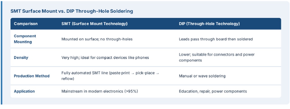
5.3 SMT vs. DIP Soldering
SMT (Surface Mount Technology) is the mainstream technology in modern electronics manufacturing. Components are mounted on the board surface and soldered automatically on SMT production lines (solder paste printing → placement → reflow oven). It offers high density, high speed, and is suitable for mass production. DIP (Through In-Package) technology, on the other hand, is a traditional method where component leads pass through the board before soldering. Although it has lower density, it is suitable for connectors, high-power components, and manual soldering. Modern PCBs typically use a combination of both technologies: SMT for critical chips and DIP for connectors and heat sinks.
© 2026 ShengYih Technologies Co., Ltd All rights reserved.